E-mail Us

DC Smart Meter Accuracy at Low Current: What Causes Measurement Deviation?

Sep 02, 2026

Table of Content [Hide]

    During normal operation, a DC measurement system may appear stable and consistent, yet the reading can begin to drift away from a reference value as the load approaches standby level. This difference is often first noticed during commissioning, calibration checks, or long-term monitoring, especially when the same circuit behaves normally at medium or high current but shows greater variation near the lower end of its range.

    This behavior does not necessarily indicate a faulty DC smart meter. At low current, the useful electrical signal becomes much smaller, so influences that are barely noticeable under heavier load begin to account for a larger part of the final reading. Sensor characteristics, zero offset, electrical noise, temperature, and signal conversion can all become more visible as current falls.

    Evaluating a DC electric meter under these conditions therefore requires more than checking its nominal accuracy specification. The current sensor, measurement range, wiring, installation environment, and internal signal processing all affect what eventually appears on the display or monitoring platform. Understanding how these factors interact makes it easier to determine whether a low-load deviation comes from the meter, the sensing method, or the wider installation.

    Why Low-Current Conditions Increase the Risk of Measurement Error

    The main difficulty at low current is that the useful signal becomes weaker while many sources of uncertainty remain almost unchanged.

    A small zero offset provides a simple example. At higher current, the offset may represent only a very small part of the total reading. As current falls, the same offset becomes more significant in proportion to the measured value. The absolute difference may remain similar, but the percentage deviation becomes much easier to notice.

    Electrical noise follows much the same pattern. Interference from nearby switching equipment, power supplies, control circuits, or the meter's own electronics may have little influence when the signal is strong. Near the bottom of the measuring range, however, the gap between useful signal and unwanted variation becomes much smaller.

    This becomes important when a DC smart meter is used in systems that spend long periods at partial load. Battery installations, solar power systems, charging equipment, telecom power supplies, and DC distribution networks can all move between heavy load and standby conditions. A meter selected mainly around peak current may not necessarily provide the best visibility in the part of the range where the system spends most of its time.

    The practical impact depends on the purpose of the measurement. A small deviation may have little consequence during a short high-power operating period. If a circuit remains lightly loaded for many hours, however, small differences can affect accumulated energy data and make genuine standby consumption harder to distinguish from measurement uncertainty.

    dc-smart-meter-accuracy-at-low-current-what-causes-measurement-deviation.jpg

    How Current Sensor Selection Influences Low-Load Accuracy

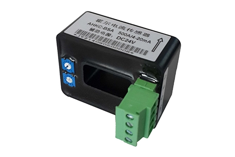
    The current sensor has a direct influence on what the meter finally receives. In many installations, the dc electric meter does not measure line current by itself. Instead, it works with a sensing element such as a shunt or a Hall-effect current sensor.

    A shunt converts current into a small voltage that changes in proportion to the current flowing through it. When the shunt, wiring, and meter input are correctly matched, this can provide stable measurement across a wide operating range. At low current, however, the voltage produced across the shunt becomes very small. Connection resistance, thermal effects, input offset, and unwanted voltage drops can then account for a larger part of the signal being measured.

    Hall-effect sensors approach the problem differently and provide electrical isolation between the conductor and the measurement circuit. Their low-load behavior depends strongly on sensor range and zero stability. If a sensor is designed for a current much higher than the circuit normally carries, everyday operation may use only a small portion of the available range.

    This is why the question is not simply whether a shunt or Hall sensor is more accurate. The better choice depends on the current profile, isolation requirement, installation environment, and how important low-current performance is to the application.

    The meter and sensor are therefore best selected together. Acrel offers DC metering solutions for different sensing arrangements and operating conditions, so its range of DC energy meters and monitoring devices is most useful when matched to the actual current profile of the system rather than only its maximum possible load.

    The Role of Zero Offset and Resolution in Small-Current Measurement

    As the measured current approaches zero, the stability of the zero point becomes increasingly important.

    In an ideal system, the meter would show exactly zero whenever no current is flowing. Real electronic circuits always contain small tolerances. Sensors, amplifiers, analog-to-digital converters, and other components can produce a residual signal even when the actual current is extremely low.

    Calibration can reduce this effect, but the zero point does not always remain perfectly fixed. Temperature changes, component drift, and sensor behavior can shift it slightly over time. For a DC smart meter operating mainly at moderate load, this movement may be almost invisible. In a standby monitoring application, it can become part of the reading itself.

    Resolution introduces another limitation. A digital measurement system converts an analog input into discrete values. If only a small part of the available input range is being used, very small changes in current become harder to distinguish reliably.

    This is also why the number of digits shown on a display should not be mistaken for true measurement capability. A DC electric meter may display several decimal places while the uncertainty of the complete measurement chain remains larger than the final digit suggests. What matters is not display resolution alone, but the useful resolution of the sensor, input circuit, converter, and processing system together.

    FactorWhat Happens at Low CurrentWhy It Matters
    Sensor RangeThe useful signal occupies a smaller part of the available rangeOffset and noise become more noticeable
    Zero OffsetA residual signal becomes more significant relative to the actual currentNear-zero readings may appear higher or lower than expected
    Measurement ResolutionVery small changes approach the effective measurement stepFine current variations become harder to distinguish
    Installation QualityInterference and unwanted voltage drops become more significantReadings may shift even when the real load changes very little
    Signal ProcessingFiltering and averaging affect how small changes appearThe reading may look steadier but respond more slowly

    Installation Factors That Can Distort DC Smart Meter Readings

    A measurement system that performs well during bench testing can behave differently once it is installed in a working electrical cabinet. At low current, details that seem minor under normal load can begin to affect the result.

    In a shunt-based system, the measured voltage can be very small. Poor sensing connections or unintended voltage drops in the wiring can then become significant enough to influence the final value. Signal cables routed close to switching conductors or power electronics may also pick up interference that becomes more visible as the useful DC signal weakens.

    Hall-effect sensors have different installation sensitivities. Nearby conductors, external magnetic fields, and the position of the measured cable can influence the sensor output. At high load, those effects may represent only a small percentage of the total signal. Near zero current, they become much easier to see.

    Temperature can introduce another layer of variation. An electrical cabinet may warm while converters, chargers, or other equipment are operating and cool again when the system enters a lighter-load state. If the sensor or meter electronics shift slightly with temperature, a change that appears to follow the load may partly reflect changing environmental conditions.

    Grounding and auxiliary power quality also deserve attention. A DC smart meter may be connected to communication networks, external power supplies, or control systems, so the measurement circuit does not always operate in complete isolation from the rest of the installation. Electrical noise or unwanted potential differences can become noticeable when the signal being measured is already small.

    For this reason, field troubleshooting should not start with the assumption that the meter itself is inaccurate. The meter, sensor, wiring, power supply, grounding, and nearby electrical environment need to be considered together before the source of the deviation becomes clear.

    How Sampling and Signal Processing Affect Partial-Load Measurement

    The signal arriving at the meter is only the beginning of the measurement process. Before a value appears on the display or reaches a monitoring platform, it is typically sampled, converted into digital data, filtered, calculated, and sometimes averaged.

    These stages can change the way partial-load behavior appears.

    Averaging is often used to make a reading easier to follow. Combining several samples reduces random variation and can make small-current measurements look more stable. The trade-off is response time. A longer averaging period may smooth the display, but genuine changes in current can take longer to appear.

    A shorter averaging window responds more quickly but allows more of the natural variation in the signal to remain visible. Neither approach is automatically better. A battery monitoring system focused on long-term energy trends may benefit from a steadier result, while a test setup looking for short current changes may need a faster response.

    Filtering becomes particularly relevant when power electronics are involved. Chargers, converters, and switching devices can create ripple on top of the DC current. A DC electric meter and a reference instrument may process that ripple differently, so their displayed values may not match exactly even when both devices are functioning correctly.

    This can cause confusion during field verification. Comparing two instruments is only meaningful when they are measuring the same point under similar conditions and are both suitable for the type of waveform present. If their sampling rates, averaging methods, or filters differ significantly, part of the apparent deviation may come from signal processing rather than from an actual measurement error.

    Reducing Measurement Deviation in Low-Current DC Applications

    Improving low-current performance starts with understanding where the system actually operates. Selecting a meter or sensor only from the maximum possible current can result in a measuring range that is unnecessarily wide for everyday conditions.

    If most operation takes place far below that range, the meter may spend much of its time working with a relatively small signal. A better-matched current range can make low-load readings more useful while still leaving sufficient margin for expected operating peaks.

    Zero behavior should also be checked under realistic conditions rather than only once during commissioning. A system tested immediately after startup may behave differently after the enclosure reaches normal operating temperature or after nearby equipment has been running for several hours.

    Installation quality can make just as much difference as equipment selection. Stable sensing connections, sensible cable routing, correct sensor position, and a reliable electrical reference all help reduce unwanted variation. If a reading changes only at certain times, comparing those changes with cabinet temperature, converter operation, or nearby electrical activity can provide useful clues.

    It is equally important to define what level of low-current performance the application actually needs. General energy monitoring, battery management, and standby-current verification do not place the same demands on a measurement system. A meter that is suitable for tracking energy trends may not be the best choice when the main objective is to measure very small currents with high confidence.

    For that reason, minimum expected current should be considered alongside maximum current, operating voltage, sensing method, and communication needs when a DC smart meter is selected. Doing so reduces the risk of finding after installation that the system performs well at higher load but not in the range that matters most.

    Conclusion

    Low-current deviation becomes more visible because the useful measurement signal is shrinking while offset, noise, sensor drift, installation effects, and conversion limits remain present. The system may not have become less stable; those influences have simply become larger in relation to the value being measured.

    This is why low-current accuracy should be treated as a property of the complete measurement chain. The dc electric meter, current sensor, wiring, zero stability, temperature, and signal processing all contribute to the result that eventually appears on the display or monitoring platform.

    For projects where standby consumption or partial-load behavior matters, these requirements are best considered before the meter and sensor are finalized. Once the expected DC voltage, normal current range, minimum operating current, and sensing method are known, Acrel can review the metering requirements and help match the measurement configuration to the application.

    Frequently Asked Questions 

    1. Why does DC smart meter accuracy change at low current?

    Because the useful signal becomes smaller while offset, noise, sensor drift, and conversion uncertainty remain present. These effects therefore account for a larger proportion of the final reading.

    2. Can an oversized current sensor reduce low-load accuracy?

    Yes. When the sensor range is much larger than the current normally being measured, the useful signal occupies only a small part of that range, making offset and noise more noticeable.

    3. Is a shunt better than a Hall sensor for low-current measurement?

    Not in every application. Shunts and Hall sensors have different sources of uncertainty. The better choice depends on current range, isolation requirements, installation conditions, and the required performance near zero current.

    4. Why does a DC electric meter show current when the load is off?

    A small residual reading may come from zero offset, electrical interference, sensor drift, or real standby consumption. Testing under a confirmed zero-current condition helps identify the source.

    5. Can installation affect DC smart meter accuracy?

    Yes. Wiring, grounding, sensor position, nearby magnetic fields, temperature, and electrical interference can all influence low-level signals, especially near the lower end of the measuring range.

    6. How can low-current DC measurement be made more reliable?

    Use a current range that matches the real operating load, verify zero stability, improve sensing connections and wiring, and evaluate the system under realistic temperature and operating conditions.


    Aaron Shi
    Aaron Shi

    Electrical Engineer Expert, Providing Service, consultant, product expert, professional manufacturer of energy efficiency management systemic solutions, and energy meters.

    References